Camera calibration of assistants 3Q0/3QD* (MFK 2.0)
For successful and correct operation of the Lane Assist camera you must: 1. Filled correct parameters 2. Properly installed Lane Assist camera 3. Correct camera encoding 4. The camera calibration procedure was performed correctly
Adaptations
Calibration target position adaptation channels do not affect camera calibration, but they can affect its operation
Block A5 (assistant camera) → Adaptation:
Calibration target position-Target 1: calibration mark 1: x-coordinate, Passat 2400 mm (Tiguan 2541 mm)
Calibration target position-Target 1: calibration mark 1: y-coordinate, Passat 745 mm (Tiguan 735 mm)
Calibration target position-Target 1: calibration mark 1: z-coordinate, Passat 1506 mm (Tiguan 1694 mm)
Calibration target position-Target 1: calibration mark 2: x-coordinate, Passat 2400 mm (Tiguan 2541 mm)
Calibration target position-Target 1: calibration mark 2: y-coordinate, Passat -745 mm (Tiguan -735 mm)
Calibration target position-Target 1: calibration mark 2: z-coordinate, Passat 1506 mm (Tiguan 1694 mm)
Calibration target position-Target 1: calibration mark 3: x-coordinate, Passat 2400 mm (Tiguan 2541 mm)
Calibration target position-Target 1: calibration mark 3: y-coordinate, Passat 745 mm (Tiguan 735 mm)
Calibration target position-Target 1: calibration mark 3: z-coordinate, Passat 846 mm (Tiguan 1106 mm)
Calibration target position-Target 1: calibration mark 4: x-coordinate, Passat 2400 mm (Tiguan 2541 mm)
Calibration target position-Target 1: calibration mark 4: y-coordinate, Passat -745 mm (Tiguan -735 mm)
Calibration target position-Target 1: calibration mark 4: z-coordinate, Passat 846 mm (Tiguan 1106 mm)
Y is the calibration points along the horizontal transverse axis,
Z is the vertical axis calibration points (varies with camera height on different vehicles).
Z is the vertical axis calibration points (varies with camera height on different vehicles).
Installing the calibration panel
Calibration layout
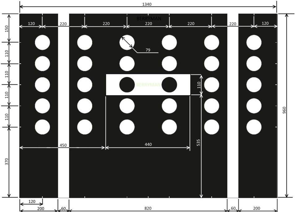
The calibration panel must be centered in front of the car and be at a distance of 1500 mm from the central axis of the front wheels, the installation height of the stand is 1570 mm from the plane on which the car stands to the top edge of the stand.
Step 1 - Position the calibration stand at a distance of 1500 mm ± 20 mm from the center axis of the vehicle's front wheels. The installation height of the stand is 1570 mm from the plane on which the car stands to the top edge of the stand. The stand must be strictly level (both vertical and horizontal), the vertical center of the stand must coincide with the longitudinal center of the car and the plane of the stand must be strictly perpendicular to the longitudinal axis of the car.
Step 2 - Perform calibration (calibration process is described below). When calibrating, enter the REAL values of the height of the wheel arches!
Calculation of poster height setting:
1200 — chamber height 535 — distance from the bottom edge of the stand to the white rectangle 110/2=55 — distance from the bottom of the rectangle to its center 960 - distance from the bottom edge to the top edge of the poster TOTAL: 1200-535-55+960=1570 (to the top edge of the poster)
1480 - camera height 535 — distance from the bottom edge of the stand to the white rectangle 110/2=55 — distance from the bottom of the rectangle to its center 960 - distance from the bottom edge to the top edge of the poster TOTAL: 1480-535-55+960=1850 (to the top edge of the poster)
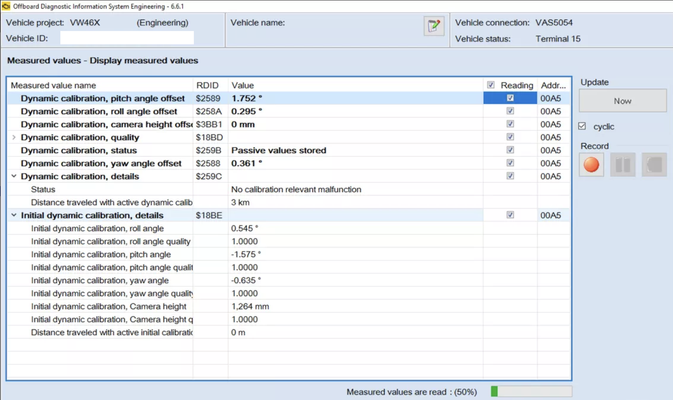
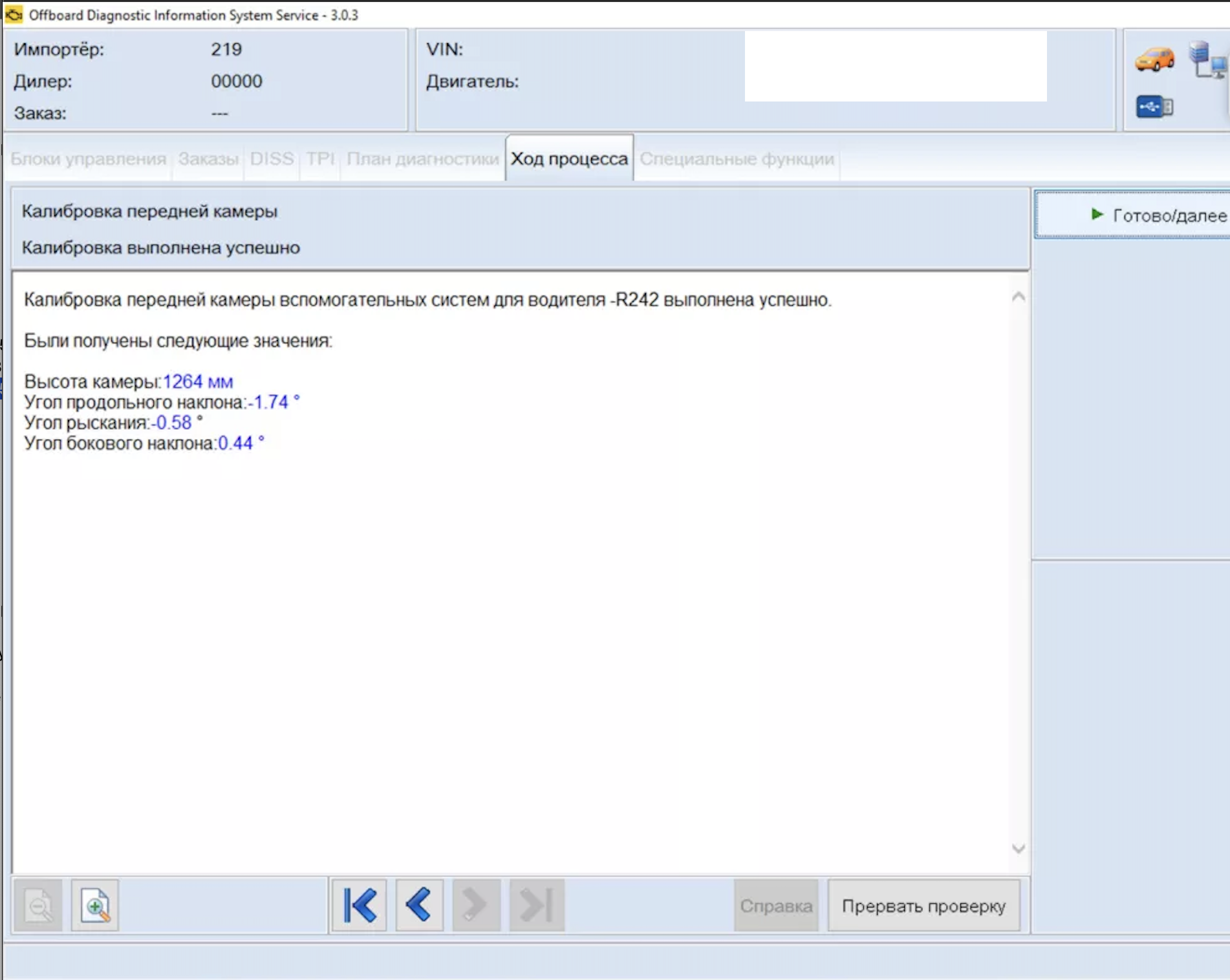
Calibration process
The calibration process lasts up to 10 seconds, after which the system will ask you to turn off the ignition, wait and turn it on again.
The angles in the results should be as close to 0 as possible.
3 degrees is the limit value at which the camera will not calibrate. In practice, angles up to 1 degree are the norm.
We carry out a test drive at a speed of more than 65 mph for 10 minutes on a marked road and check the dynamic calibration values (calibration while driving).
The maximum value of dynamic calibration angles is 3 degrees.
As soon as this angle is greater, the camera will display an error and the assistants will turn off.
If the dynamic calibration, namely the longitudinal inclination angle, is above 1.5 degrees, then this indicates that during calibration the stand was not installed correctly or the wrong parameters were filled in.
1. Odis Service – “Data bus topology”, block A5, right-click “Block Identification”, block A5 will become active in the list of blocks.
- Select the item "Front sensors for driver assistance systems (BOSCH)"
- Right click on block A5 – measuring equipment
- Select A5 - calibration
- In the next 4 steps, enter the REAL values for the height of the wheel arches.